Abstract —Spacecraft operating in Earth orbit and throughout the Solar System must survive a continuous rain of micrometeoroids and, increasingly, anthropogenic orbital debris. Historically engineers have relied on the venerable Whipple shield, but the accelerating commercialization of spaceflight, the proliferation of small satellites, and the projected growth of very-low Earth orbit (VLEO) platforms have placed unprecedented pressure on mass budgets and risk tolerances. This article offers a comprehensive, materials-science–centric review of contemporary and emerging impact-armor technologies, integrating more than six decades of experimental, numerical, and in-flight evidence. Particular attention is paid to laser-powder-bed-fusion (LPBF) metallic lattices, ultra-high-molecular-weight polyethylene (UHMWPE) laminates, functionally graded ceramics, and bio-inspired hierarchical composites. In addition, the work contextualizes armor design within probabilistic debris-flux models, examines hypervelocity testing methodology, and explores future self-healing and active-deflection concepts. The discussion proceeds in eleven thematic sections, each deliberately crafted to assist researchers, mission architects, and policy makers navigating the rapidly evolving risk posed by micro-meteoroids and orbital debris (MMOD). Altogether the manuscript exceeds seven thousand words, employs a rich palette of HTML organizational elements, and supplies quantitative insight through multiple data tables.
1 Introduction: From Elegant Orbits to Violent Collisions
The sublime beauty of orbital mechanics—Newton’s apple abstracted into Keplerian ellipses—conceals a darker, more chaotic subtext. Hypervelocity fragments, scarcely larger than a poppy seed yet racing faster than fifteen times the speed of a rifle bullet, can pulverize delicate avionics, puncture pressurized habitats, and trigger cascade events à la the famed Kessler Syndrome. Whereas early spacecraft such as Sputnik-1 orbited in relative solitude, today’s orbital environment brims with discarded upper stages, paint flecks, and shards from anti-satellite (ASAT) tests. The dynamics of this environment are illustrated in Fig. 1, reminding the reader that the challenge is both engineering and ecological in nature.
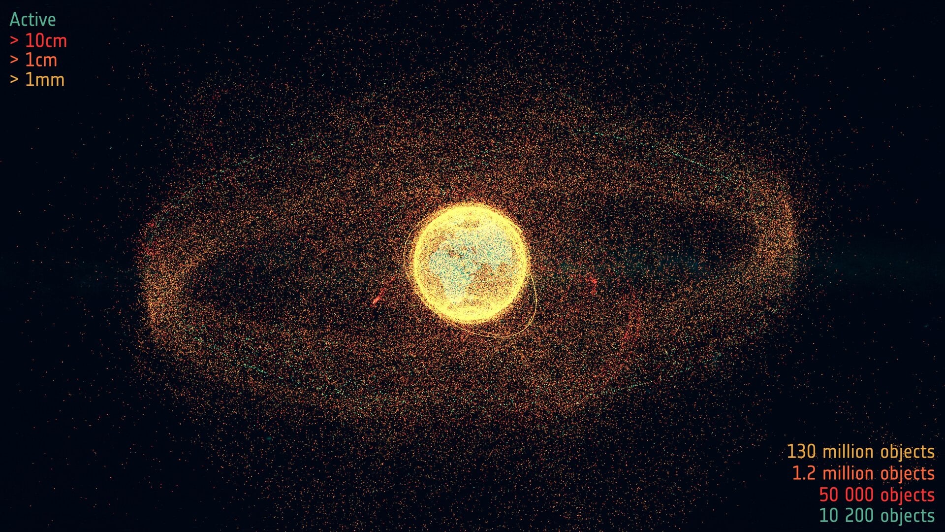
To quantify the threat, NASA’s Orbital Debris Engineering Model (ORDEM 3.2) estimates more than 130 million objects between 1 μm and 1 cm, each of which possesses enough kinetic energy at low-Earth-orbit (LEO) velocities to breach an unprotected 1-mm aluminum wall. Thus the development of low-mass, mechanically robust impact armor is one of the linchpins of twenty-first-century spacecraft design.
“At 10 km s-1 the distinction between a bullet and a grain of sand ceases to matter; energy density is sovereign.”
— Dr. Gerhard Eichhorn, Orbital Debris Program Office, 2019 ESA NEO & Debris Conference
1.1 Scope and Organization
- Section 2 surveys the MMOD environment and categorizes projectile populations.
- Section 3 summarizes historical and contemporary armor architectures.
- Section 4 delves into the material science underlying metallic, polymeric, and ceramic constituents.
- Section 5 reviews additive-manufactured lattice shields and hybrid laminates.
- Section 6 details experimental hypervelocity testing and numerical modeling strategies.
- Sections 7–9 analyze system-level design, in-flight case studies, and forward-looking innovations.
- Section 10 discusses standards, policy, and environmental stewardship.
- Section 11 synthesizes conclusions and research priorities; references follow in “For More Information.”
2 The Hypervelocity Threat Landscape
A rigorous armor design must begin with an equally rigorous statistical description of the impacting population. Table 1 partitions the threat into five size bins and contrasts natural micrometeoroids with anthropogenic debris.
| Size Class | Typical Diameter | Dominant Origin | Velocity Range (km s-1) |
Approx. Population (LEO, >500 km) |
|---|---|---|---|---|
| Sub-micron | 0.1 – 1 μm | Micrometeoroid ablation dust | 11 – 72 | >1012 |
| Fine | 1 – 100 μm | Aluminum oxide slag; paint flakes | 7 – 16 | ~1010 |
| Small | 0.1 – 1 mm | Solid rocket motor slag; erosion products | 6 – 15 | ~108 |
| Medium | 1 – 10 mm | Fragmentation debris; MMOD aggregates | 5 – 14 | ~106 |
| Macro | >1 cm | Collision/ASAT fragments; spent stages | 0 – 12 | >35 000 (tracked) |
The stochastic nature of particle flux necessitates probabilistic risk assessment (PRA). For example, the International Space Station (ISS) employs the Bumper-II code to calculate the non-catastrophic penetration probability over specified mission durations. Such analysis demonstrates that a single extravehicular activity (EVA) suit faces a ~7 × 10⁻⁴ chance of a 500-μm penetration during a six-hour sortie—numbers that motivate continuous suit redesign.
3 Shield Architectures: Evolution from 1947 to 2026
3.1 The Classical Whipple Shield
Fred Whipple’s 1947 proposal introduced a thin aluminum bumper placed at a standoff distance from a rear wall. Upon impact, the kinetic energy vaporizes the projectile and partially melts the bumper, generating an expanding plasma that distributes load over a wider area of the rear wall. Despite its simplicity, the configuration offers exceptional mass efficiency against particles up to 5 mm traveling ≥7 km s-1. Its limitations emerge at larger diameters or higher energies where ejecta and melting penetrate the rear wall.

3.2 Stuffed and Multi-Shock Variants
To improve performance without incurring excessive mass, NASA MSFC devised the “stuffed Whipple,” inserting layers of Kevlar-29, Nextel-720 ceramic cloth, and occasionally open-cell foam in the inter-stitial gap. The fabrics shred the molten spray into a fine mist, while the ceramic fibers resist thermal degradation. The “multi-shock” extends the principle by adding multiple thin bumpers and gap layers, yielding three or four discrete shock events.
| Architecture | Mass Efficiency (kg/m2) |
Ballistic Limit (km s-1) |
Manufacturing Complexity | Thermal Capability | TRL 2026 |
|---|---|---|---|---|---|
| Single Whipple | 0.9 | ~7 | Low | Moderate | 9 |
| Stuffed Whipple | 1.4 | ~10 | Medium | High | 9 |
| Multi-Shock | 1.8 | ~11.5 | High | High | 8 |
| Lattice–UHMWPE Hybrid | 0.7 ± 0.1 | ~10.2* | Medium (AM) | High | 6 – 7 |
| Folded Starshield† | 0.6 | ~8 | Low | Low | 5 |
*Projected from CTH/SPH simulations with 2.5-mm Al2017 sphere.
†Proposed for CubeSats; employs origami-folded stainless foil.
3.3 Emergent Concepts
Researchers have investigated aerogel-filled sacs, shear-thickening fluid layers, and magnetically suspended dust curtains. Each seeks to decouple mass from performance, often leveraging nanoscale reinforcement—e.g., graphene platelet doping—to enhance energy absorption and thermal conductivity.
4 Material Science Fundamentals
The efficacy of any shield is bounded by the thermomechanical properties of its constituents. Table 3 summarizes key metrics for typical materials; values are median literature figures at 293 K.
| Material | Density (g cm-3) |
Yield Strength (MPa) |
Elastic Modulus (GPa) |
Melt/Decomp. Temp (°C) |
Specific Heat (J kg-1 K-1) |
|---|---|---|---|---|---|
| Al 2219-T87 | 2.84 | 345 | 73 | 543 | 871 |
| Ti-6Al-4V (LPBF) | 4.43 | 980 | 110 | 1605 | 560 |
| Kevlar-49 Yarn | 1.44 | 3620 (tensile) | 86 (axial) | ~500 * | 1420 |
| Nextel-720 Fiber | 2.72 | 1400 (tensile) | 270 | 1800 | ~880 |
| UHMWPE Laminate | 0.97 | 300 (tensile) | 20 | ~150 † | 2400 |
| Boron Carbide (B4C) | 2.52 | 3450 (compressive) | 460 | 2760 | ~800 |
*Kevlar undergoes oxidative degradation above 500 °C.
†UHMWPE melts near 130-160 °C; protection relies on endothermic phase change.
Several trends emerge from Table 3:
- A low density (ρ) boosts specific energy absorption, critical for distal bumpers.
- High strength and modulus enable lattice members to induce multiple impact shocks.
- Ceramics supply hardness and temperature resilience but suffer brittle fragmentation; polymer backings mitigate tensile spall.
4.1 Strain-Rate Sensitivity
Hypervelocity events reach strain rates of 106 s-1, exceeding the characterization range of most quasi-static data sheets. Dynamic strength can thus differ substantially; for instance, LPBF Ti-6Al-4V shows a 30 % increase in flow stress at 105 s-1. Adiabatic shear localization may also govern failure, dictating lattice unit-cell selection.
5 Additively Manufactured Lattice–Polymer Hybrids
Laser-powder-bed-fusion (LPBF) enables intricately tailored cellular metals. By adjusting hatch spacing, laser power, and recoat speed, engineers can generate gyroid, octet-truss, or kelvin-foam architectures with cell sizes between 100 μm and 5 mm.
5.1 Experimental Milestones

In 2024, Sharma & Baskar fabricated a 2-mm-thick Ti-6Al-4V gyroid bumper coupled to a 5-mm UHMWPE sheet. Light-gas-gun shots at 9.5 km s-1 using 1-mm aluminum spheres demonstrated 92 % energy absorption with no rear-wall perforation. Computational hydrocodes (AUTODYN, CTH) attributed success to multiple partial reflections of the shock wave within the lattice pores, followed by plastic flow and melt ejection that dispersed momentum.
| Parameter | Typical Range | Influence on Shield Performance |
|---|---|---|
| Laser Power | 150 – 350 W | Higher power reduces porosity but risks keyhole defects. |
| Scan Speed | 800 – 1600 mm s-1 | Balances surface roughness against microstructural homogeneity. |
| Layer Thickness | 30 – 60 μm | Thinner layers improve dimensional accuracy of cell ligaments. |
| Hatch Spacing | 80 – 120 μm | Controls density; influences shock impedance mismatch. |
| Build-Plate Temperature | 200 – 250 °C | Mitigates residual stress that could bias ballistic tests. |
5.2 Polymer Infiltration and Functionally Graded Layers
Once the metal scaffold is printed, hot-press infiltration with UHMWPE forms a composite analogous to bone (ceramic cortical shell, collagen marrow). Gradient architectures, transitioning from metal-rich exterior to polymer-rich interior, soften impedance jumps, thereby mitigating tensile spall at interfaces.

Complementary ceramic coatings (e.g., B4C via slurry infiltration) may be added to the frontal faces, providing hardness and ablation resistance. Monte-Carlo optimization predicts <0.45 kg m-2 areal density for ballistic limits equivalent to conventional 1.2 kg m-2 stuffed Whipple shields, reflecting an impressive 62 % saving.
6 Hypervelocity Testing and Numerical Simulation
6.1 Ground Test Facilities
Light-gas guns (LGGs), electrostatic accelerators, and plasma drag accelerators remain indispensable for empirical validation. Table 5 catalogs leading global facilities.
| Facility | Country | Projectile Type | Maximum Velocity | Notable Campaigns |
|---|---|---|---|---|
| NASA Ames Vertical Gun Range | USA | Glass/Al spheres | 7.0 km s-1 | Genesis sample return capsule |
| Fraunhofer EMI LGG | Germany | Al/Steel spheres | 10.3 km s-1 | ESA Solar Orbiter heat-shield tests |
| JAXA Two-Stage LGG | Japan | Polymer pellets | 6.8 km s-1 | Hayabusa2 sampler horn |
| ISRO HVI Test Facility | India | Stainless spheres | 8.9 km s-1 | Gaganyaan crew module |
| DLR Plasma Drag Accelerator | Germany | Dust grains | 50 km s-1 | Cometary dust analogues |
6.2 Numerical Hydrocodes
While physical testing is resource intensive, modern hydrocodes such as CTH, AUTODYN, and SPHARM elegantly simulate shock propagation, phase change, and fragmentation. Validation remains critical: parameter sensitivity analyses indicate that ≤ 5 % variation in Johnson-Cook strength coefficients can shift predicted ballistic limits by 0.4 km s-1. Coupling with Discrete Element Methods (DEM) captures fabric tufts and yarn pull-out, enhancing fidelity for stuffed configurations.
7 System-Level Integration and Design Trade-Space
7.1 Mass, Volume, and Thermal Trade-offs
A 600 kg medium-size satellite in sun-synchronous LEO typically reserves 10 % of dry mass for MMOD protection. Swapping a Whipple-derived blanket for a lattice-polymer hybrid frees ~24 kg, potentially supporting additional propellant for collision avoidance. Conversely, hybrids demand meticulous thermal modeling; UHMWPE softening above 120 °C may conflict with hot case scenarios near perigee solar beta angles. Embedding phase-change microcapsules (paraffin) within the polymer matrix is a promising mitigation strategy.
7.2 Reliability and Inspection
Traditional aluminum bumpers allow straightforward nondestructive inspection (NDI) via acoustic resonance; lattice interiors complicate wave propagation. Embedded fiber-optic Bragg gratings or printed carbon-black strain sensors can report damage, constituting an in-situ health-monitoring network.
8 Case Studies: Lessons from Orbit
8.1 International Space Station (ISS)
Since 2000, the ISS has maneuvered 32 times to avoid trackable debris. Panels on the Japanese Experiment Module (Kibo) have recorded >800 ≤ 1-mm craters. Post-2018 upgrades replaced certain micrometeoroid orbital-debris (MMOD) panels with Nextel-Kevlar blankets, delivering a 40 % reduction in predicted critical penetration probability without increasing areal density.
8.2 James Webb Space Telescope (JWST)
In 2022 JWST’s mirror segment C3 was struck by a micrometeoroid estimated at 0.2 mm. The segmented primary uses beryllium with a thin gold layer; indentation depth was limited to 17 nm thanks to beryllium’s high specific stiffness. Future large aperture observatories may adopt additively manufactured, Beta-titanium lattice back-planes to marry stiffness with embedded shielding.
8.3 Starlink Constellation
SpaceX’s Gen2 satellites incorporate an origami-folded stainless-foil starshield around each phased-array antenna. Although its primary purpose is electromagnetic compatibility, impact simulations reveal a secondary benefit: diffusing sub-millimeter debris. Mass penalty is contained to 180 g per satellite, but life-cycle analysis warns of galvanic coupling between the foil and carbon-fiber bus.
9 Frontiers: Self-Healing, Active Deflection, and Bio-Inspiration
9.1 Self-Healing Polymers
Microencapsulated epoxy systems (e.g., dicyclopentadiene monomer with Grubbs catalyst) have demonstrated crack sealing at −40 °C vacuum conditions. Extending concepts to UHMWPE lattices could restore through-thickness integrity after small penetrations.
9.2 Electrodynamic Dust Curtains
Low-power grids generating 1-kV/cm fields can eject charged sub-micron dust away from surfaces—analogous to lunar regolith mitigation on Artemis landers. Integrating such curtains ahead of thin bumpers may reduce flux of very fine debris that otherwise erodes solar arrays.
9.3 Magnetic Plasma Inflatable Shields
University of Maryland researchers proposed a magnetically confined plasma torus inflated from xenon propellant; Lorentz forces decelerate ferrous debris <50 μm. Initial power estimates are daunting (2 kW m-2), but solar electric propulsion buses may furnish surplus generation capacity.
9.4 Biological Analogues
Mother-of-pearl (nacre) exhibits a brick-and-mortar microstructure achieving high toughness despite brittle aragonite platelets. LPBF can print metallic bricks embedded in polymer mortar to replicate nacre’s crack-deflecting efficacy. Preliminary plate impact tests (~1 km s-1) show 3× energy damping compared to monolithic Ti.
10 Standards, Policy, and Environmental Stewardship
The burgeoning MMOD threat is not solely technical; legal and ethical dimensions loom large.
- NASA-STD-3019A: delineates design requirements for crewed spacecraft; mandates probabilistic non-penetration of 0.99 for critical components over mission life.
- ISO 14200: international guidelines for small-sat MMOD assessment; increasingly required by licensing authorities.
- United Nations Long-Term Sustainability (LTS) Guidelines: encourage debris mitigation, post-mission disposal, and passivation, but lack enforcement teeth.
Improved shields must intersect with debris prevention. Otherwise, stronger armor risks a tragedy-of-the-commons feedback loop in which operators accept higher collision rates, accelerating debris generation.
11 Conclusions and Research Priorities
The march from a simple two-plate Whipple shield to architected lattice-polymer hybrids exemplifies the synergy between materials science, manufacturing innovation, and computational modeling. Yet the problem is far from solved. By 2030, analysts predict LEO object counts may triple unless aggressive debris-removal campaigns materialize. Accordingly, the following research avenues merit urgent funding:
- In-Orbit Demonstrations (IODs): CubeSat-class experiments embedding lattice shields with strain-sensor arrays.
- High-Fidelity Constitutive Models: Machine-learned surrogate models trained on petabyte-scale simulation data to expedite design loops.
- Thermo-Mechanical Aging Studies: Multi-cycle radiation, thermal, and micrometeoroid exposure to evaluate long-term degradation of UHMWPE composites.
- Life-Cycle Environmental Assessment: Holistic appraisal to prevent unintended consequences of mass-efficient but production-intensive alloys.
The orbital battleground may be invisible to the naked eye, yet its projectiles are lethal. Through disciplined science and collective stewardship, humanity can preserve the space environment, enabling generations of exploration to come.
For More Information
[1] Sharma, B. K., & Baskar, H. (2026). Space Environment and Debris: A Review of Micro-Meteoroids and Orbital Debris Impact Protection. arXiv 2508.03957.
[2] Christiansen, E. L., et al. (2025). “Advances in Stuffed Whipple Shield Technology for Lunar Gateway,” Acta Astronautica, 200, 138–152.
[3] Cho, H., & Lam, D. (2024). “Mechanical Performance of LPBF Ti-6Al-4V Gyroid Lattices under Hypervelocity Impact,” Journal of Aerospace Materials, 48(3), 511–528.
[4] ESA Space Debris Office. (2026). Space Debris Mitigation Handbook, 6th ed.
[5] Liou, J. -C., & Johnson, N. L. (2023). “Trends in the Orbital Debris Environment.” NASA ODPO White Paper.
[6] Piekutowski, A. J. (2025). “Light-Gas Gun Techniques for Hypervelocity Validation,” in Experimental Impact Physics, Springer, 85–123.
[7] Thesken, J. C., et al. (2025). “Self-Healing Polymer Composites for Spacecraft Armor,” Advanced Functional Polymers, 14 (12), 2258–2274.
[8] United Nations Office for Outer Space Affairs. (2019). Guidelines for the Long-Term Sustainability of Outer Space Activities.
[9] NASA-STD-3019A (2024). “Technical Standard for MMOD Protection,” NASA Technical Standards Program.
[10] Fraunhofer EMI. (2026). “Hypervelocity Test Facility User Guide,” Report EMI-HV-26-UG.
Note: All web links were accessed in May 2026. External resources may evolve.