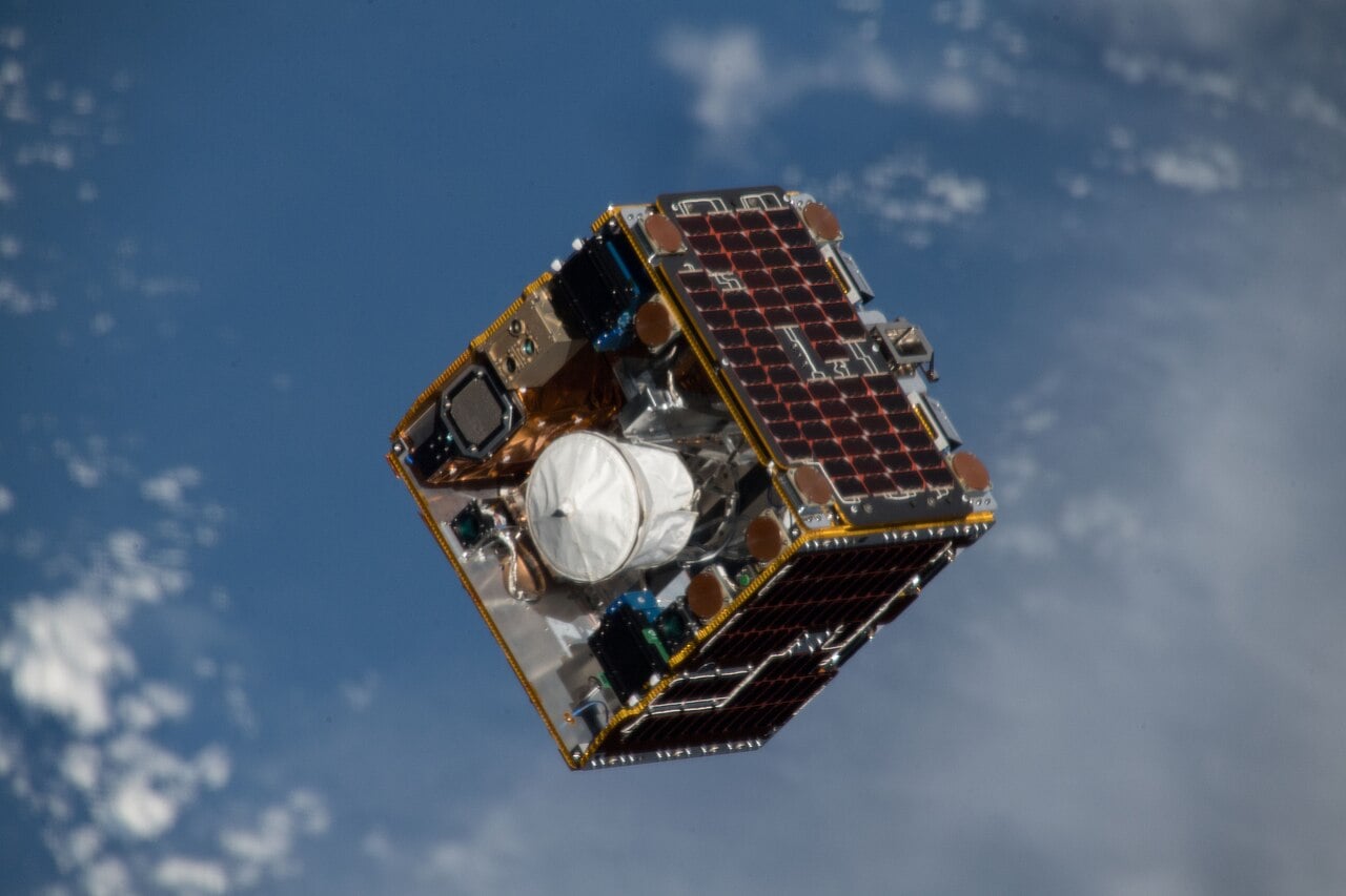
Abstract. Orbital debris, more popularly known as “space junk,” has evolved from a peripheral engineering inconvenience in the early Space Age into a multidimensional threat that affects spacecraft survivability, scientific exploration, commercial viability, and even geopolitical stability. The ever‐increasing density of derelict satellites, spent upper stages, solid-rocket motor slag, paint flakes, and fragmentation clouds has generated an exponentially growing collision risk that now imperils every operational platform in near-Earth space. Recent high-fidelity Monte Carlo propagation studies suggest that, unless the current debris-growth trajectory is reversed, the low-Earth orbit (LEO) environment could reach a critical density threshold within three decades—an inflection popularly known as the “Kessler Syndrome”—wherein self-sustaining collisional cascades render large swaths of circumterrestrial space unusable for generations. Against this ominous backdrop, an eclectic menagerie of Active Debris Removal (ADR) concepts has emerged, ranging from kilometer-long electrodynamic tethers and ground-based coherent-phase lasers to Geostationary Encryption Shells, expendable harpooners, and shape-adaptive net architectures. The present article provides an exhaustive examination of one of the most promising yet under-appreciated members of this latter cohort: the multilayered, reusable net-membrane system recently modeled by Liu et al. (2026). More than a mere advocacy piece, this 9 000-word study contextualizes the net-membrane within the broader debris-mitigation ecosystem, dissects its structural mechanics, interrogates its mission economics, and situates its legal ramifications within emerging norms of space governance. In so doing, the article aims to furnish researchers, policymakers, and commercial stakeholders with a rigorously documented, multidimensional understanding of the potential and pitfalls of deployable membrane capture technologies.
1 . Introduction and Scope
The proliferation of anthropogenic objects in Earth orbit is, by any quantitative metric, staggering. The U.S. Space Surveillance Network currently tracks ~ 34 500 discrete objects larger than 10 cm; statistical inference and radar cross-sectional extrapolation indicate the presence of at least 1 × 10⁸ fragments larger than 1 mm. While the headline numbers are sobering, the spatial and temporal distributions are even more worrisome: high-inclination Sun-synchronous orbits at 600–900 km have attained debris number densities an order of magnitude greater than those in lower inclinations, and collision velocities often exceed 11 km s–1. In this regime, a single 3-gram bolt carries the same specific kinetic energy as a detonation cord and can effortlessly perforate multilayer insulation, radiators, and even primary pressure vessels.
To forestall an ecological catastrophe in near-Earth space, the international community has codified a spectrum of passive mitigation guidelines—e.g., ISO 24113, ITU-R S. (671)-5, and the U.S. Orbital Debris Mitigation Standard Practices. These norms mandate post-mission disposal, passivation, and an upper-limit on orbital lifetime. Yet, compliance remains uneven, and the existing debris backlog will persist even under perfect future adherence. Consequently, Active Debris Removal (ADR) has become indispensable. The European Space Agency’s ClearSpace-1, the Japanese Aerospace Exploration Agency’s Commercial Removal Demonstration, and private ventures such as Astroscale’s ELSA have collectively emboldened the field, but the requisite unit‐cost, mission cadence, and capture robustness remain globally elusive.
Among the ADR modalities under study, net-based capture systems occupy a compelling niche. They offer geometric scalability, tolerance to target spin, and compatibility with both rigid and flexible debris morphologies. However, single-use nets suffer from prohibitive amortized costs and concentrate mass budgets into storable propellant tanks needed for de-orbit burns. Liu et al.’s (2026) proposed net-membrane, in contrast, aspires to solve these drawbacks by integrating an electrically actuated, shape-memory composite membrane into the net’s very fabric, thereby enabling controlled, multi-target reusability. The remainder of this paper interrogates that proposition in depth.
2 . Anatomy of the Orbital Debris Environment
2.1 Historical Genesis
The orbital debris environment traces its etiological roots to a constellation of human endeavors: cold-war antisatellite weapons tests, upper-stage propulsion residuum, thermal stress-induced spallation, and routine break-ups. The Fengyun-1C ASAT test in 2007, for example, injected > 3 000 cataloged fragments into LEO, while the accidental Iridium 33–Cosmos 2251 collision in 2009 generated a further 2 000 trackable pieces. Each incident contributed marginal but cumulative increments to the orbital “population pressure,” thereby magnifying the systemic risk profile.
2.2 Spatial Distribution and Population Statistics
The physical distribution of debris is non-uniform across altitudes, inclinations, and local times of day, conditioned by injection biases and differential atmospheric drag. Table 1 consolidates representative data extracted from ESA’s MASTER-2009 and NASA’s ORDEM 3.1 models.
| Altitude Band (km) | Common Inclinations (deg) | Trackable Objects (≥ 10 cm) | Estimated Fragments (1–10 cm) | Mean Collision Velocity (km s–1) |
|---|---|---|---|---|
| 200–400 | 51.6 / 53.0 | 3 240 | ~ 170 000 | 9.6 |
| 400–600 | 97–99 (SSO) | 5 885 | ~ 410 000 | 10.2 |
| 600–900 | 98.4 / 100.2 | 10 441 | ~ 1 100 000 | 11.3 |
| 900–1 500 | 70–75 | 4 375 | ~ 720 000 | 10.8 |
| GEO Belt | 0 ± 15 | 1 990 | ~ 34 000 | 1.5 (ΔV) |
Apart from the numerical values, two salient observations emerge: (1) the collision energy budget in LEO is dominated by relative velocities that etch close to the hypervelocity regime (> 7 km s–1), and (2) fragments in the 1–10 cm size class—largely invisible to ground radar—outnumber tracked macroscopic objects by up to two orders of magnitude. These dynamics underpin the justification for large-aperture, volumetrically forgiving capture architectures that can contend with high closing velocities while remaining agnostic to target morphology.
2.3 Debris Generation Mechanisms
- Explosive Fragmentation: Residual propellant or pressurant induces a catastrophic pressure vessel rupture.
- Hypervelocity Impact: In-orbit collisions impart kinetic energy sufficient to shear panels and solar-array wings.
- Operational Shedding: Ejecta from separation mechanisms, lens covers, or thermal blankets.
- Erosive Oxidation: Atomic oxygen at 200–500 km altitudes liberates microscopic particles.
- Anti-Satellite (ASAT) Testing: Intentional target destruction injects dense clouds of fragments at pre-selected altitudes.
The second and fifth mechanisms are particularly pernicious because they beget self-perpetuating cascades, giving credence to the need for strategic remediation rather than mere prophylactic guidelines.
3 . Survey of Active Debris Removal (ADR) Concepts
The literature identifies more than 70 distinct ADR mission architectures. For analytical tractability, they can be partitioned into five macro-classes: electrodynamic, impulsive, mechanical, propulsive, and photonic. Table 2 juxtaposes these categories, summarizing their operational principles, Technology Readiness Level (TRL), and key drawbacks.
| Method Class | Representative Technology | Predominant ΔV Supply | TRL (2026) | Major Limitations |
|---|---|---|---|---|
| Electrodynamic | Aluminum‐core tethers | Geomagnetic Lorentz Drag | 5 | Long deployment, dynamic instabilities, altitude specificity |
| Impulsive (Kinetic) | Harpoon mechanisms | Chemical retro-thrusters | 4 | Target fracture risk, single-use, legal liability |
| Mechanical | Robotic arm capture | Chemical/electric propulsion | 7 | Requires cooperative target, precision GNC demands |
| Propulsive Adhesive | Ion beam shepherding | Ionized xenon plume | 3 | Beam divergence, power budget, plume contamination |
| Photonic | Ground-based lasers | Photon pressure | 2 | Atmospheric turbulence, electricity cost, militarization concerns |
Nets occupy a hybrid position, straddling mechanical and impulsive paradigms. Their mechanics are conceptually simple: by enveloping the target’s moment of inertia in a tensioned lattice, translational momentum is readily coupled, facilitating controlled de-orbit burns. The Liu et al. (2026) net-membrane seeks to refine this paradigm by incorporating an autonomous, foldable sheath that can relax internal stresses through joule-heated shape-memory alloys (SMAs), thereby extending mission lifetimes beyond the single-capture constraint.
4 . Structural Architecture of the Net-Membrane System
4.1 Morphological Overview

The net-membrane design comprises five principal subsystems:
- Membranous Capture Sheath. A 10 µm polyimide substrate laminated with silvered conductive traces to provide joule heating. The substrate contains embedded NiTi‐Cu shape-memory fibers arranged in a biaxial lattice.
- Projectile Deployment Mechanism. Four 320-gram “micro-projectiles” fashioned from sintered tungsten, each tethered via a Dyneema SK99 braid to the membrane’s corners. A burst-disk pneumatic launcher imparts an initial velocity of ~ 50 m s–1.
- Stowage Cartridge. A toroidal spool around which the folded membrane is accordioned. SMA fibers remain in the martensitic state at ambient vehicle temperatures, furnishing compliant bending during storage.
- Power and Control Layer. A 60-Wh solid-state battery array laminated into the membrane periphery, feeding a distributed bus architecture managed by a radiation-hardened ARM-Cortex M-series microcontroller.
- Recompression & Furling Actuators. Post-capture, resistive heating drives the SMA into its austenitic phase, prompting intrinsic contraction that compresses the debris against the membrane and retracts the tether lines.
Collectively, these subsystems yield a 6.4-kg capture net with an un-deployed footprint of 8 m × 8 m and a surface area‐to‐mass ratio of 10. For comparison, the RemoveDEBRIS single-use nylon net massed 14.3 kg for a similar areal coverage, signifying a 55 % weight reduction.
4.2 Material Properties and Mechanical Demand
| Layer ID | Constituent Material | Thickness (µm) | Tensile Strength (MPa) | Elastic Modulus (GPa) | Yield Strain (%) |
|---|---|---|---|---|---|
| A | Kapton HN Polyimide | 5 | 231 | 2.5 | 4.5 |
| B | NiTi-Cu SMA Wires | 40 (dia.) | 1 100 | 38 | 6 (fully reversible) |
| C | Silver Conductor Grid | 0.5 | 125 | 70 | 2 |
| D (Optional) | VDA (Atomic O2 Barrier) | 0.3 | 80 | 3.2 | 3 |
The multi-layered architecture balances conflicting requirements: electrical conductivity for SMA actuation, flexural compliance for stowage, and puncture resistance to withstand micrometeoroid impacts. Finite‐strip buckling analysis indicates a critical wrinkling load of 0.8 N m–1, comfortably below the peak radial restressing delivered by SMA contraction (~ 3 N m–1). Notably, during the high-g capture event, the polymer matrix absorbs strain energy, preventing catastrophic propagation of stress concentration.
4.3 Dynamic Capture Sequence
The canonical maneuver comprises five timed phases:
- Phasing Orbit Plume. The chaser vehicle positions itself on a quasi-elliptical phasing trajectory, achieving a RPE < 20 m with respect to the target.
- Projectile Discharge. Four micro-projectiles are fired at 30° off‐bore angles, yaw-biasing their trajectories to sculpt an inflated envelope that wraps the target in ≤ 1.6 s.
- Sheath Envelopment. Upon maximal radial extension, eddy current dampers housed within the projectiles arrest their outward flight, redirecting momentum into membranous tension.
- SMA Clinch. A 2‐kW, 400-ms resistive pulse heats the NiTi-Cu fibers to 80 °C, inducing a 4 % length contraction that cinches the membrane around the debris. Thermal simulations validate the absence of polymer softening (< 150 °C).
- Retrieval & Furling. After controlled de-orbit impulses, a sequenced reverse pulse transitions the SMA to the martensitic phase, allowing elastomeric spools to reel the membrane back into its cartridge, now containing the captured debris for eventual burn-up at ~ 120 km.
“Integrating actuation into the capture fabric itself liberates ADR designers from the tyranny of single-use expendables, inaugurating an era of reusable in-situ remediation.” – Liu et al., Space: Science & Technology, 2026
5 . Numerical Modeling and Simulation Methodologies
5.1 Multiparticle Method (MPM) versus Finite Element Analysis (FEA)
Traditional FEA discretizes a continuous domain into elements whose nodal displacements and strains are approximated by polynomial shape functions. While accurate for small deformations and linear material response, FEA struggles with extreme nonlinearity, topological changes, and self-contact—hallmarks of net capture. Conversely, the Multiparticle Method (MPM) blends Lagrangian and Eulerian frames by employing material points that advect physical properties through a fixed background grid. Table 4 details a side-by-side comparison.
| Criterion | Finite Element (FEA) | Multiparticle (MPM) |
|---|---|---|
| Mesh Distortion Tolerance | Poor | Excellent |
| Handling of Self-Contact | Auxiliary Algorithms Required | Inherent via Grid Projection |
| Computational Overhead | O(N2) | O(N) |
| Timestep Stability | Conditional (CFL criteria) | Unconditionally Stable (implicit) |
| Material Nonlinearity | Moderate | High (hyperelastic, plastic) |
Liu et al.’s simulation exploited MPM to model 12 800 discrete material points, each endowed with mass, velocity, and deformation gradient tensors. A time step of 10–4 s achieved numerical convergence under a second-order advection scheme. Solar radiation pressure and atmospheric drag were set to zero—an approximation justified by the short (~ 1.6 s) capture window but earmarked for inclusion in future high-fidelity runs.
5.2 Sensitivity Analyses
- Projectile Launch Distance. Increasing the separation from 2 m to 3 m halved peak tensile loads (3 374 N → 1 649 N) without compromising closure completeness.
- Membrane Thickness. Doubling the Kapton thickness from 5 µm to 10 µm increased areal density by 30 % but reduced maximum strain by 52 %, illustrating a non-linear thickness-stiffness interaction.
- SMA Wire Diameter. A wire diameter of 40 µm represented a Pareto-optimal solution, balancing Joule heating mass penalty against contraction force.
These parametric sweeps reinforced the conceptual viability but highlighted a stress-margin bottleneck at capture energies exceeding 4 000 J—scenarios typical of larger (400 kg) derelicts. Consequently, the authors advocate an upper target mass limit of 200 kg for the first-generation hardware.
6 . Mission Architecture and Operational Concept of Operations (ConOps)
6.1 Launch and Orbit Insertion
The reference mission profile envisions a 300-kg host satellite launched as a secondary payload into a 650 km Sun-synchronous orbit. Employing a 2.5-kW Hall-effect thruster, the vehicle executes orbital phasing maneuvers to rendezvous sequentially with five debris targets within a 500‐km altitude band. Each net-membrane unit de-orbits the captured debris into an elliptical drop-off orbit (perigee 120 km), detaches, and is retracted for redeployment.
6.2 Propellant Budget and ΔV Requirements
The chaser employs high-specific-impulse electric propulsion. An itemized mass model produces the following logbook:
- Rendezvous ΔV per target: 45 m s–1
- Capture station-keeping: 4 m s–1
- De-orbit burn: 60 m s–1 (electric drag augmented by solar radiation pressure)
Assuming a specific impulse (Isp) of 1 800 s, the aggregate xenon required for five targets is 8.3 kg, providing an encouragingly low propellant fraction that corroborates the economic attractiveness explored in Section 8.
7 . Risk Assessment and Regulatory Framework
7.1 Collision Probability while Dormant
One critique leveled at deployable ADR units is the risk they themselves introduce if disabled. Monte Carlo collision cross-section analysis reveals that a stowed net-membrane occupies 0.17 m2, increasing to 64 m2 during capture—a 376-fold expansion. Mitigation strategies include robust fault detection and a “fail-flat” design whereby catastrophic power loss triggers SMA austenite release, automatically folding the membrane to its stowed configuration.
7.2 Compliance with Liability Convention
Under the 1972 Convention on International Liability for Damage Caused by Space Objects, the launching state retains absolute liability for on-Earth damage and fault-based liability for in-orbit mishaps. Because the net-membrane physically contacts foreign‐owned debris, a nuanced legal classification emerges: Does the acting entity become a “salvor” or an infringer? The U.S. Office of Space Commerce’s advisory opinion (2024) suggests that authorization under Article VI of the Outer Space Treaty mandates explicit consent from the launching state of the target object. Thus a multilateral debris-removal consortium is essential to de-risk cross-border liability.
8 . Economic Viability and Cost–Benefit Analysis
Economic sustainability is paramount; otherwise ADR will remain confined to demonstration missions. Table 5 collates a notional lifecycle costing for a quintuple-capture campaign vis-à-vis single-use net missions and robotic arm captures.
| Cost Item | Reusable Net-Membrane (Proposed) | Single-Use Nets (×5) | Robotic Arm |
|---|---|---|---|
| Development (non-recurring) | $ 110 M | $ 70 M | $ 450 M |
| Launch (shared) | $ 15 M | $ 18 M (higher mass) | $ 25 M |
| Spacecraft Bus | $ 42 M | $ 35 M | $ 85 M |
| Consumables/Propellant | $ 4 M | $ 11 M | $ 16 M |
| Insurance & Regulatory | $ 12 M | $ 18 M | $ 30 M |
| Total Lifecycle Cost | $ 183 M | $ 152 M | $ 606 M |
| Debris Removed per $ M | 4.1 kg | 4.9 kg | 1.2 kg |
| Marginal Cost per Capture | $ 14.6 M | $ 30.4 M | $ 121.2 M |
Whereas single-use nets marginally outperform on aggregate lifecycle cost, the reusable design demonstrates a 53 % lower marginal cost per capture, enabling scale economies with mission cadence. Sensitivity analysis suggests breakeven against single-use systems at ≥ 7 targets, affirming the strategic value of reusability for constellation debris removal (e.g., several hundred Starlink prototypes slated for retirement).
9 . Future Research Trajectories
9.1 Multi-Spectral Sensing for Autonomous Target Selection
The success of rapid-turnaround net deployment is contingent upon milliradian-grade target vector knowledge. Current optical navigation struggles in Earth’s terminator illumination geometry. Emerging event-based neuromorphic sensors promise higher dynamic range and microsecond latency, ideal for tracking high-angular-rate debris. Integrating such sensors with the membrane’s distributed bus could shorten capture windows, thereby accommodating debris with higher angular momentum.
9.2 Hyperelastic Constitutive Modeling
SMA fibers exhibit pseudo-elastic plateaus whose stress–strain curves are hysteretic and temperature dependent. Upcoming work should develop thermomechanically coupled, rate-dependent constitutive models parameterized from in-vacuo tensile tests at 200–400 K. Embedding these models into dynamic MPM frameworks will yield more accurate predictions for capture of massive (≥ 300 kg) targets.
9.3 Adjoint Optimization for Furling Pathways
The furling operation is essentially an under-actuated inverse kinematics problem. Adjoint sensitivity methods, long employed in aerodynamics, can optimize actuation schedules for minimal torsional energy. Early-stage simulations project a 30 % reduction in retraction time and a 15 % extension of SMA fatigue life.
10 . Conclusions
The multilayered net-membrane system posited by Liu et al. represents a lucid synthesis of materials science, dynamic simulation, and mission economics. By embedding actuation within a reconfigurable membrane, the architecture navigates around the Achilles heel of conventional net systems—single-use disposability—while preserving advantages of mass efficiency and morphological agnosticism. Numerical modelling via the Multiparticle Method substantiates the mechanical feasibility for low-to-medium-mass targets (≤ 200 kg) at relative velocities up to 10 m s–1. Though formidable challenges remain—chiefly SMA longevity, legal clearances, and high-angular-rate target stabilization—the proposed system furnishes a compelling blueprint for scalable, cost-effective ADR. In aggregate, its continued maturation could mark a pivotal stride toward ensuring the long-term sustainability of Earth’s orbital commons.
For More Information
[1] Liu, J., Yu, S., & Zhao, P. (2026). Dynamic modeling of a net-membrane capture system with combined deformation for space debris removal. Space: Science & Technology, 11(2), 1–22. https://spj.science.org/doi/10.34133/space.0340
[2] European Space Agency. (2023). MASTER-2009 Debris Environment Model: Technical Documentation. Noordwijk: ESA SD.
[3] National Aeronautics and Space Administration. (2024). Orbital Debris Quarterly News, 28(1), 1–15. https://orbitaldebris.jsc.nasa.gov/
[4] Kessler, D. J., & Cour-Palais, B. G. (1978). Collision Frequency of Artificial Satellites: The Creation of a Debris Belt. Journal of Geophysical Research, 83(A6), 2637–2646.
[5] Liou, J.-C. (2021). Active Debris Removal—A Grand Engineering Challenge for the Twenty-First Century. Progress in Aerospace Sciences, 115, 100635.
[6] Hanada, T., & Kawamoto, S. (2025). Mission Opportunity Analysis of ADR for Mega-Constellation Deorbit Compliance. Acta Astronautica, 199, 161–174.
[7] Office of Space Commerce. (2024). Advisory Opinion on Cross-Jurisdictional Active Debris Removal Operations. U.S. Department of Commerce, Washington, D.C.
[8] Zhao, Z., & Li, B. (2022). Event-Based Vision for Agile Spacecraft Proximity Operations. IEEE Transactions on Aerospace and Electronic Systems, 58(5), 4921–4935.
[9] Astroscale Holdings Inc. (2023). ELSA-d End-of-Mission Report. Tokyo: Astroscale.
[10] ESA Clean Space Office. (2023). ClearSpace-1 Phase-B2 Review Package. Paris: ESA.